


It is expected additional fasteners will penetrate through any wall sheathing to attach cladding or cladding attachments to the framing. With some minor exceptions, the standardized test methods for Water-resistive Barriers (WRB) and Air Barriers (AB) [1] do not consider a range of cladding attachment penetrations.
GP Gypsum commissioned RDH Building Sciences in Waterloo, Ontario to establish and conduct water penetration demonstration testing using ASTM E331 methodology that would stress the DensElement™ Barrier System at the cladding fastener penetrations. The same high-stress water penetration at cladding fastener penetration tests were also done with both thin and thick-mil fluid applied barriers applied over glass mat gypsum sheathing. Another DensElement™ Barrier System wall was also tested with two inches of XPS sheathing attached. With these side-by-side comparisons, when leaks were detected, it could be determined what circumstance most contributed to the leak.
Scope
Three water-resistive barrier systems (WRBs) with cladding fastener penetrations were tested: The DensElement™ Barrier System, a thin-mil fluid-applied WRB, and a thick-mil fluid applied WRB. The DensElement™ Barrier System and fluid-applied WRBs were tested with two different cladding attachment clips – one FRP and one thermally-broken metal, and two different Z Girt arrangements (applied both flange up and flange down). Five 4’x8’ test wall panels were constructed for the purpose of this testing. A sixth test wall panel was constructed to demonstrate water penetration when an XPS exterior insulation board is attached using only long screws.
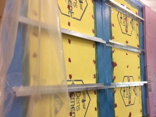
Picture 1: The DensElement™ Barrier System with Z Girts installed with flanges up and down. The Z Girts are installed both tight and spaced from the WRB. Far right test wall shows XPS attached.
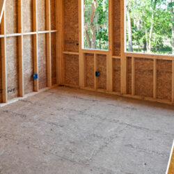
The DensElement™ Barrier System is a gypsum sheathing, water-resistive barrier and air barrier combination consisting of DensElement™ Sheathing and PROSOCO R-Guard® FastFlash® fluid applied flashing. When the sheathing joints, openings, penetrations, sheathing fasteners, and material transitions are properly sealed, the system meets uniform code requirements for use as a water-resistive barrier, air barrier and a UL classified Type X gypsum sheathing.
Both thin-mil and thick-mil fluid-applied coatings were applied over glass mat gypsum sheathing. These systems also represent gypsum sheathing, water-resistive barrier and air barrier combinations that are commonly used in the market and meet uniform code requirements.
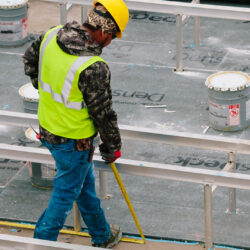
The cladding attachment clips were fixed back to framing using self-drilling, self-tapping screws provided by the manufacturer. The Z Girts were attached using self-drilling, self-tapping screws commonly specified for this purpose.
For the exterior-insulated test wall, two inches of XPS rigid insulation was attached to the DensElement™ Barrier System panel using to 4 inch long self-drilling, self-tapping screws and with large (1 in. dia.) plastic cap washers. The top edge of each piece of XPS was cut with a bevel back towards the wall so some water was forced behind the insulation.
The demonstrations were set up to essentially take the various assemblies to failure. Failure was deemed to occur when water was seen to be leaking at the cladding attachment fastener location.
The demonstrations did not allow any other locations for water to penetrate; i.e. there were no windows, pipe penetrations, joints, material transitions, or other designed water entry locations beyond the cladding attachment fasteners.
Test Methods
Cladding attachment clips and Z Girts were attached using two methods: a) tightly against the sheathing or WRB surface and b) spaced away from the sheathing or surface with different spacer thicknesses to allow water to flow behind the attachment.
The rigid insulation board was installed in a similar manner: with one section tight to the sheathing and two other sections spaced away from the sheathing at different spacing thicknesses to create a gap between the back of the insulation and the exterior face of the sheathing.
The test wall and water spray nozzles were set up per ASTM E331. The walls were then subjected to water spray duration and negative air pressure loads exceeding ASTM E331 protocol for code compliance.
Water application rate was 7.5 gallons per hour per sq. ft. instead of 5.0 gallons per hour per sq. ft.
Water was applied to the surface for 60 minutes at each pressure instead of 15 minutes at the single code required pressure of 140 Pa. Instead of the total test time length being 15 minutes, it was 5 hours! The wall(s) were tested for 60 minutes each at; 0 Pa, 300 Pa, 600 Pa, 900 Pa, and 1250 Pa. The last stage is equal to sustained winds of 100 mph!
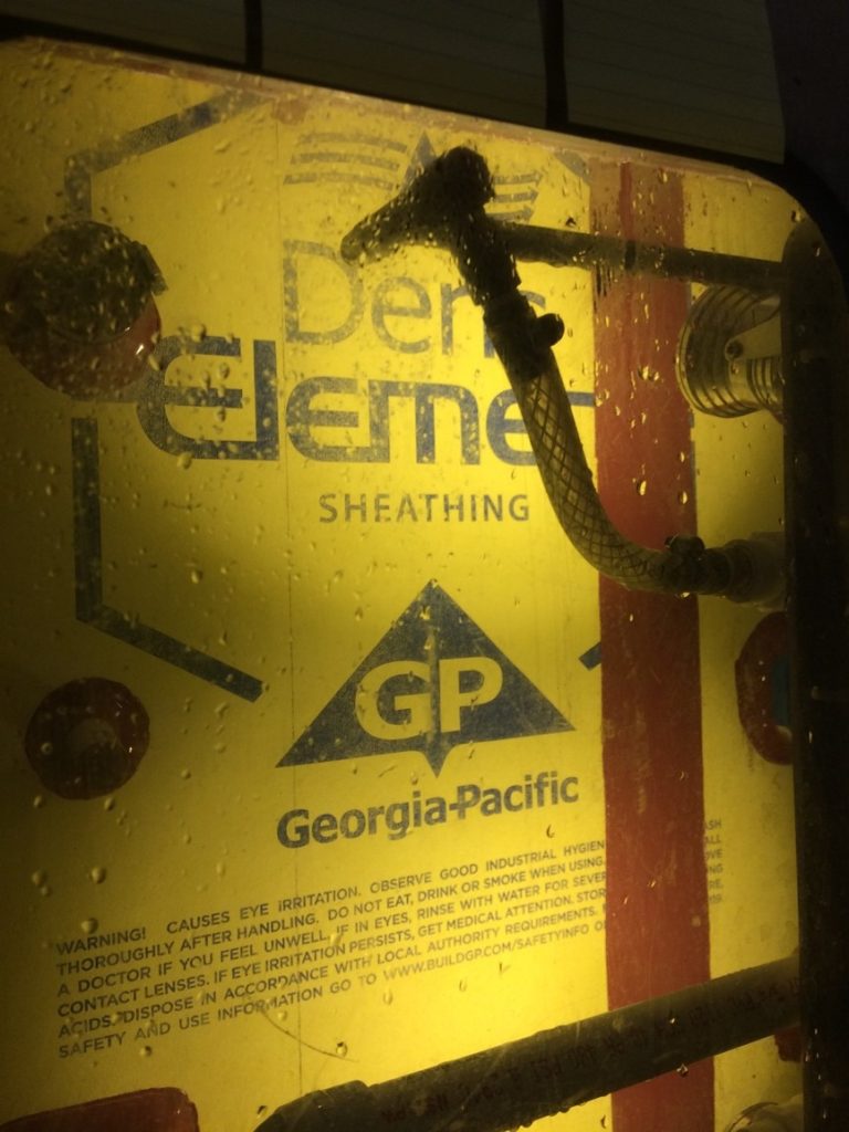
Picture: The DensElement™ Barrier System tested per ASTM E331.
Summary of Results
The demonstration produced leaks at the cladding attachment fasteners on all three WRB systems and where the fasteners for the XPS exterior insulation penetrated the sheathing.
The testing demonstrated how the cladding fasteners are attached to the surfacing has the most bearing on why the assemblies leaked when subjected to these conditions. It made little difference if the cladding attachment was fastened through the DensElement™ Barrier System or through the fluid- applied WRB membranes applied over glass mat sheathing.
The testing demonstrated that if water finds a penetration, it doesn’t make a measurable difference if the penetration was through DensElement™ sheathing, thin-mil fluid applied WRB, or thick-mil fluid-applied WRB.
In general, if the cladding fasteners were installed tight to the sheathing or fluid-applied WRB surface, water did not penetrate around the fastener, and the assemblies did not leak.
Likewise, If the cladding fastener was installed so it was adequately spaced away from the wall surface, allowing the water to drain behind the cladding attachment, the assemblies didn’t leak.
Most of the leaks happened when the space between the WRB surface and the cladding attachment was just enough for water to enter behind the attachment but not wide enough for the water to effectively drain. In this case, it is believed a head of water was formed and leaked through the fastener penetration given the amount of water exposure and the high negative pressures.
Under normal weather conditions (normal defined as ASTM E331 test criteria) water did not penetrate into the wall cavity through the cladding attachment fasteners in any of the assemblies.
Best Practices to Reduce Risk Under Severe Conditions
The tests also reveal that, under normal weather conditions (normal defined as ASTM E331 test criteria) water did not penetrate into the wall cavity through the cladding attachment fasteners in any of the assemblies.
The test results do show what represents high wind (71, 85, 100 mph) with sustained heavy rain conditions, (defined as above ASTM E331 test criteria). Under these extreme conditions water may penetrate into the wall cavity through these cladding attachment fasteners in any of the assemblies.
To reduce the potential for water to enter the cavity in the occasional extreme weather event, additional details and guidance should be considered with the goal of maintaining high performance when climate, exposure, and construction factors stress the wall assemblies.
The following Table 1 suggests best practices for any cladding attachment penetration through any type of WRB based on the demonstration testing and observations.
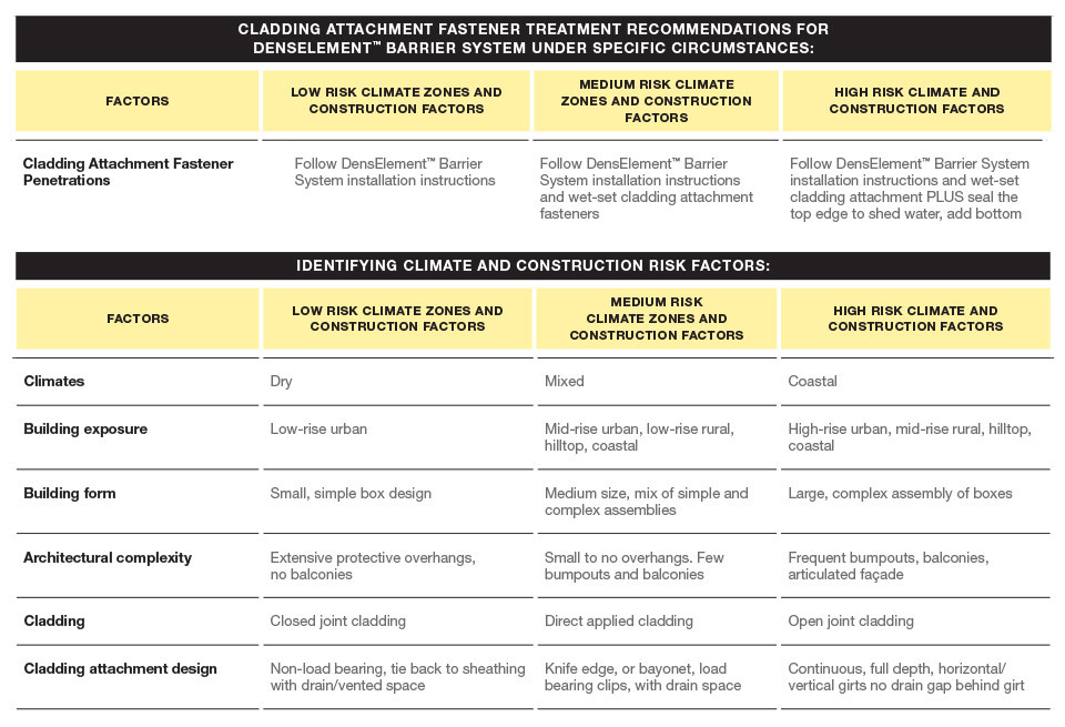
The tables represent conditions and applications when it is not practical that every attachment will be fastened tight or properly spaced from the surface—regardless of the WRB surface, and in this case, DensElement™ Barrier System. It suggests extra steps to account for penetrations and minimize the potential for leakage under low, medium and high-risk conditions.
As a high-risk example, a mid-rise building in Seattle, WA., with numerous architectural features, and open-joint rainscreen cladding should consider additional cladding attachment sealing beyond attach tight or attach with space. Wet-setting the cladding attachment elements (e.g. clips or Z Girts) and adding a bead of sealant along the top of each attachment would provide a higher-performance seal for that type of exposure in that type of climate. Additional attachment sealing would be wasteful in a similar building in Phoenix, AZ.
As a high-risk example, a mid-rise building in Seattle, WA., with numerous architectural features, and open joint rainscreen cladding should consider additional cladding attachment sealing beyond attach tight or attach with space. Wet-setting the cladding attachment elements (e.g. clips or Z Girts) and adding a bead of sealant along the top of each attachment would provide a higher-performance seal for that type of exposure in that type of climate.
Providing Drying Potential Can Reduce Impact of Minor Leaks Through Cladding Fasteners
The demonstration testing shows minor leaks can happen in major rain and wind events, although the test conditions may only occur rarely (e.g. once every 5 years). To reduce the risk of moisture damage when a small amount of water does get into the wall cavity, it is also important that the wall assembly can dry. The high vapor permeability of DensElement™ Barrier System provides excellent drying capability. Many fluid applied WRBs, have moderate to low vapor permeance and, when applied over glass mat gypsum sheathings, effectively reduce drying capability of the sheathing and the assembly. Water penetration through cladding attachment fasteners is typically minor compared to other pathways. However, using a vapor permeable fast-drying WRB assembly reduces the moisture damage potential even further.
The high vapor permeability of DensElement™ Barrier System provides excellent drying capability.
Summary
The testing demonstrates that where there is a hole, under extreme water and wind, leaks may occur regardless of the water-resistive barrier used.
Most of the leaks happened when the space between the DensElement™ Barrier System or the fluid-applied WRB and the cladding attachment was just enough for water to enter behind the attachment but not big enough for the water to effectively drain. The attachment was neither tight to the surface or sufficiently spaced to promote drainage.
The guidelines in Tables 1 and 2, are suggested best practices to reduce the potential for leaks. These, in combination with the provision of drying potential to address small amounts of water when it does get into the wall assembly, will provide the highest level of performance.
[1] The standard test methods for assessing water barrier performance includes, but not limited to, test methods included in ICC-ES AC 212. Air tightness tests include, but are not limited to, ASTM E2178 and ASTM E2357